el-kabel.de >>
light-by-wire.com >>
el-kabel.de >>
light-by-wire.com >>
el-kabel.de >>
light-by-wire.com >>
Light by Wire
deutsch >>
|
|
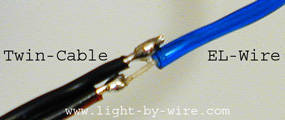
On one end the EL Wire needs a soldered connection with an inverter that supplies the special
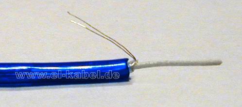
EL-voltage. The other end of the wire stays electrically open, but should be sealed against moisture
with a drop of "Super-Glue" (Don't use normal Paper Adhesive!) On the connection side remove the outer plastic-cover of the EL-wire by 1 to 1.5 cm. Use a stripper, a blade or melt the cover with the hot soldering iron. Be careful not to hurt the underlying two tiny wires - these are the outer electrodes! Wrap these two wires together and bend them to the side. The solid central wire is covered with the porous luminescence material. This thin layer needs to be scratched off by 2 to 3mm length to allow a soldered contact to the metal core. |
|
|
|
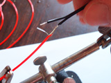
Strip the twin-cable from the inverter in two steps so that the blank copper ends can not
touch each other. Solder the longer end of the twin-cable to the two wires of the outer
electrode and the shorter to the inner core of the EL-Wire. No need to check the polarity because EL-Wires run on 1 to 2kHz alternating voltage. Now the Glow-Wire should already light up when the inverter is switched on. To fix the fragile connection seal it with at least 3 cm heat-shrink tube. Let the covered connection cool down a little before switching on the inverter. Done! |
|
|
If installations do require a certain distance between Inverter and EL-Wire an extension cable can be set in between.
Any kind of twin-cable is suitable, the length is not restricted.
Further see the hints at our Q & A >> |
| Multiple sections of Neon Wire can be connected to one EL-inverter. Serial and parallel circuits are illustrated below. Only the inverter should be strong enough to drive the total length of all sections. |
|
|
|
|
 Serial Connection / In Line
 Parallel Connection via a Starpoint